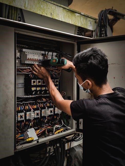
A manual transfer switch enables safe switching between two power sources, ensuring uninterrupted power supply during outages. It is crucial for installing backup generators, providing a reliable connection. The wiring diagram acts as a roadmap, guiding electricians through connections, ensuring safety and compliance with electrical standards. Key components and symbols in the diagram help simplify the installation process, making it accessible for both professionals and DIY enthusiasts. Understanding the diagram is essential for proper setup and functionality of the transfer switch system.
1.1 What is a Manual Transfer Switch?
A manual transfer switch is a device that allows users to safely switch between two power sources, such as a primary utility supply and a backup generator. It provides a reliable way to transfer power during outages, ensuring uninterrupted operation of essential circuits. The switch is typically installed between the main electrical panel and the backup generator, enabling manual control over the power source. It must be compatible with the power rating of the electrical system to ensure safe and efficient operation. Proper installation, guided by a wiring diagram, is critical for functionality and safety.
1.2 Importance of a Wiring Diagram for Installation
A wiring diagram is essential for the safe and correct installation of a manual transfer switch. It provides a clear visual representation of the connections, ensuring that each wire is properly routed and connected. This minimizes the risk of electrical hazards, such as short circuits or fires, and ensures the system functions reliably. The diagram also helps comply with electrical codes and standards, guaranteeing a legally compliant installation. Additionally, it simplifies the process for installers, reducing errors and saving time. Overall, a wiring diagram is crucial for achieving a safe, efficient, and code-compliant manual transfer switch installation.
Understanding the Wiring Diagram
A wiring diagram simplifies the installation process by illustrating the electrical connections and components of the manual transfer switch. It provides a clear, visual guide for installers to ensure proper setup, safety, and functionality of the system.
2.1 Key Components of the Wiring Diagram
The wiring diagram for a manual transfer switch includes essential components such as the main power source, backup generator, transfer switch, circuit breakers, and grounding wires. These elements are clearly labeled to ensure a safe and efficient installation. The diagram highlights the connections between the utility power, generator, and the transfer switch, providing a visual guide for installers. It also illustrates the flow of electricity and the role of each component in maintaining power continuity. Understanding these components is crucial for proper system functionality and safety.
2.2 Symbols and Notations Used in the Diagram
The wiring diagram uses standardized symbols and notations to represent key elements such as switches, circuit breakers, and power sources. Circles often denote switches, while lines represent wires connecting components. Symbols for generators, utility power, and grounding points are clearly marked. Notations like “GEN” for generator and “UTILITY” for main power help clarify connections. These symbols ensure the diagram is universally understood, simplifying the installation process. Proper interpretation of these symbols is essential for ensuring safety and functionality during setup. Always refer to the legend or key provided with the diagram for accurate identification of each element.

Installation Process
The installation involves preparing the site, connecting wires according to the wiring diagram, and ensuring all safety standards are met. Proper grounding and circuit testing are essential.
3.1 Preparing for Installation
Before installation, review the wiring diagram to understand connections and components. Ensure all necessary tools and materials are available. Disconnect power sources and verify voltage levels using a multimeter. Identify the main electrical panel and backup generator locations. Label circuits and wires for clarity. Consult the manufacturer’s manual for specific instructions. Ensure compatibility between the transfer switch and generator. Grounding the system is critical for safety. Double-check local electrical codes and regulations. Proper preparation ensures a smooth and safe installation process, minimizing risks and potential errors during setup.
3.2 Step-by-Step Wiring Instructions
Start by connecting the main power source to the transfer switch input terminals, ensuring proper alignment with the wiring diagram. Next, link the backup generator to the switch’s output terminals, matching the voltage and phase requirements. Ground the system by attaching the grounding wire to the designated terminal. Secure all connections tightly to prevent loose wires. Use a multimeter to verify voltage levels and ensure no power is present before testing. Finally, simulate a power outage to test the transfer switch functionality, confirming smooth transition between power sources. Always follow safety guidelines and manufacturer instructions.

Safety Considerations
Ensure all power sources are disconnected before starting work. Use a multimeter to verify zero voltage. Avoid contact with live wires to prevent electric shock. Always follow local electrical codes and manufacturer guidelines for safe installation and operation.
4.1 Electrical Safety Precautions
When working with a manual transfer switch, always disconnect power sources to avoid electric shock. Use a multimeter to confirm zero voltage before starting. Wear insulated gloves and safety goggles for protection. Ensure the work area is well-lit and clear of flammable materials. Follow NEC guidelines and manufacturer instructions to prevent accidents. Never touch live wires or components. If unsure, consult a licensed electrician. Proper grounding is essential to prevent electrical hazards. Regularly inspect wiring for damage or wear.
4.2 Grounding Requirements
Proper grounding is critical for safe operation of a manual transfer switch. Connect the grounding wire from the switch to the grounding bar in the main electrical panel. Ensure continuity between the generator’s grounding system and the house wiring. Use the correct size of grounding wire as specified by local codes. Verify that all connections are secure and free from corrosion. Regularly inspect the grounding system to ensure it meets NEC standards. Proper grounding prevents shock hazards and ensures reliable operation of the transfer switch during power outages.

Selecting the Right Transfer Switch
Selecting the right transfer switch involves matching its power rating to your electrical load and ensuring compatibility with your generator and wiring system for safe, reliable operation.
5.1 Power Rating and Compatibility
Selecting a transfer switch with the correct power rating ensures it can handle the electrical load without overheating or failing. Compatibility with the generator’s voltage and amperage is crucial for safe operation. Always match the switch’s rating to the maximum power requirements of your connected circuits. Refer to the wiring diagram to identify the appropriate size and type of switch for your system. Proper compatibility prevents damage and ensures reliable power transfer during outages. Consult manufacturer manuals and guides for specific recommendations on selecting the right model for your setup.
5.2 Types of Manual Transfer Switches
Manual transfer switches are available in various types to suit different applications. Single-phase switches are ideal for residential use, handling 120/240V systems, while three-phase switches are designed for commercial and industrial settings, supporting 230/400V systems. Portable and fixed transfer switches offer flexibility, with portable options suitable for temporary setups and fixed models for permanent installations. The wiring diagram provides clear connections for each type, ensuring compatibility with generators and main panels. Understanding the differences helps in selecting the right switch for specific power requirements and system configurations.

Common Applications
Manual transfer switches are commonly used in residential, commercial, and industrial settings to ensure reliable power backup during outages. Wiring diagrams simplify their installation for safe, efficient power transfer.
6.1 Residential Use
In residential settings, manual transfer switches are essential for connecting backup generators to home electrical systems. They allow homeowners to safely switch power sources during outages, ensuring continuous electricity for critical circuits like lighting, HVAC, and appliances. Wiring diagrams provide clear instructions for installing these switches, helping to identify key connections and ensure proper setup. Homeowners can select specific circuits to prioritize, making the system customizable to their needs. This setup enhances safety and reliability, preventing power surges and electrical hazards.
By following the wiring diagram, residents can efficiently manage their generator’s power distribution, maintaining comfort and security during emergencies. Regular testing and maintenance, as outlined in the diagram, further ensure the system’s longevity and effectiveness. This makes manual transfer switches a practical and indispensable solution for residential power backup needs.
6.2 Commercial and Industrial Use
In commercial and industrial settings, manual transfer switches are vital for ensuring uninterrupted power supply during outages. These switches handle higher currents and three-phase power systems, making them ideal for large facilities. Wiring diagrams play a crucial role in installing and configuring these switches, ensuring compatibility with industrial-grade equipment. They are commonly used in factories, hospitals, and data centers to maintain operations. The diagrams guide technicians in connecting multiple circuits and ensuring compliance with industrial safety standards. This ensures reliable power distribution and minimizes downtime, making manual transfer switches indispensable for commercial and industrial applications.

Testing and Maintenance
After installation, test the system to ensure proper functionality. Check connections, switches, and overall performance under load conditions. Regular maintenance is crucial for reliability.
Inspect wiring, clean contacts, and verify switch operation to prevent failures. Schedule periodic professional inspections to maintain optimal performance and safety standards over time.
7.1 Testing the System After Installation
After installing the manual transfer switch, thoroughly test the system to ensure proper functionality. Start by inspecting all connections to confirm they are secure and correctly matched according to the wiring diagram. Simulate a power outage to verify smooth transition between the main power source and the backup generator. Check if the switch operates seamlessly and the system stabilizes under load. Monitor for any unusual behavior, such as flickering lights or tripped breakers, which could indicate wiring issues. Ensure the system automatically reverts to the main power source when it is restored. Finally, review the manual for specific testing recommendations to guarantee safety and reliability.
7.2 Routine Maintenance Tips
Regular maintenance ensures the manual transfer switch operates efficiently and safely. Inspect all connections and wires for signs of wear or damage, cleaning any corrosion. Lubricate moving parts to prevent stiffness and ensure smooth switching. Test the switch periodically under load to confirm proper functionality. Check for loose screws or terminals and tighten as needed. Refer to the manufacturer’s manual for specific maintenance recommendations. Keep the surrounding area clear of debris to prevent overheating. Schedule annual professional inspections to identify and address potential issues before they escalate. This routine care extends the lifespan and reliability of the system.

Troubleshooting Common Issues
Common issues include faulty connections, switch malfunctions, or power supply problems. Check wiring diagrams for loose wires or incorrect connections. Test the transfer switch under load to identify faults. Ensure proper grounding and verify circuit compatibility. Refer to the manufacturer’s guide for specific troubleshooting steps. Addressing these issues promptly ensures reliable operation and safety.
8.1 Identifying Faults in the Wiring
Identifying wiring faults in a manual transfer switch involves checking for loose connections, incorrect wiring, or overloaded circuits; Consult the wiring diagram to verify connections. Common issues include miswired terminals, damaged wires, or improper grounding. Use a multimeter to test for continuity and voltage drops. Check circuit breakers and fuses for tripped or blown conditions. Ensure all connections match the diagram and are secure. Addressing these faults promptly prevents system malfunctions and ensures safe operation. Regular inspections and adherence to safety standards are crucial for maintaining reliability.
8.2 Resolving Switch Malfunctions
Resolving manual transfer switch malfunctions involves diagnosing and addressing issues like faulty contacts or misalignment. Start by checking connections and ensuring proper alignment. Use a multimeter to test for continuity and voltage at the terminals. Consult the wiring diagram to verify correct configurations. Replace worn-out or damaged components, such as contacts or springs. Lubricate moving parts if necessary. After repairs, test the switch by simulating a power transfer to ensure smooth operation. Regular maintenance and inspections can prevent recurring malfunctions and ensure reliable performance. Always follow safety guidelines when working with electrical systems.

Advanced Configurations
Advanced configurations optimize power distribution, offering flexibility and scalability for complex electrical systems. These setups ensure reliable energy management, adapting to diverse load requirements and enhancing system efficiency.
9.1 Multi-Circuit Transfer Switches
Multi-circuit transfer switches are designed to manage multiple electrical loads, offering flexibility for complex power systems. These switches allow for the simultaneous transfer of several circuits between two power sources, ensuring uninterrupted power supply. They are ideal for applications requiring precise control over multiple loads. The wiring diagram for such switches highlights separate connections for each circuit, enabling individual control and monitoring. This configuration enhances system reliability and scalability, making it suitable for both residential and industrial settings. Proper installation ensures efficient energy distribution and safety across all connected circuits.
9.2 Three-Phase Transfer Switches
Three-phase transfer switches are designed for industrial and commercial applications requiring high-power handling. They enable seamless switching between two three-phase power sources, ensuring continuous operation. The wiring diagram for these switches typically includes three hot wires and a neutral connection, accommodating voltages like 230V/400V. Proper installation ensures safe and efficient power distribution. These switches are ideal for heavy-duty equipment and demanding environments. Their complex wiring requires precise setup, often necessitating professional expertise to maintain reliability and safety in three-phase power systems.

Legal and Code Compliance
Ensure compliance with national and local electrical codes when installing a manual transfer switch. Adherence to safety standards is crucial to avoid legal issues and ensure safe operations.
10.1 National and Local Electrical Codes
Installing a manual transfer switch requires strict compliance with national and local electrical codes, such as the NEC (National Electric Code). These codes ensure safety and proper functionality. Local regulations may vary, so it’s crucial to consult regional authorities. Permits and inspections are often mandatory to verify compliance. Adhering to these standards prevents legal issues and guarantees reliable power transfer. Always reference the latest code updates and consult licensed professionals if unsure. Compliance ensures the system operates safely and efficiently, protecting both people and property.
10.2 Compliance with Safety Standards
Compliance with safety standards is essential for manual transfer switch installations. Adherence to certifications like UL (Underwriters Laboratories) and IEC (International Electrotechnical Commission) ensures the switch is safe and reliable. Wiring diagrams must align with these standards to prevent hazards like electrical fires or shocks. Regular inspections and maintenance are required to uphold safety protocols. Manufacturers test switches to meet these standards, but installers must follow guidelines to ensure ongoing compliance. Safety standards protect users and property, making them a critical aspect of any installation. Always verify certifications before purchasing or installing a transfer switch.

Additional Resources
Consult manufacturer manuals, online tutorials, and wiring diagrams for detailed guidance. Videos and guides provide step-by-step instructions for successful installation and operation of manual transfer switches.
11.1 Manufacturer Manuals and Guides
Manufacturer manuals provide comprehensive wiring diagrams and installation guides for manual transfer switches. These resources include detailed step-by-step instructions, safety protocols, and troubleshooting tips. They ensuring compliance with electrical codes and standards. Diagrams outline connections for generators, panels, and circuits, while guides offer practical advice for selecting the right switch. Consulting these manuals is essential for a successful and safe installation. They are available in downloadable formats or as part of product packaging, making them accessible for both professionals and DIY enthusiasts. Always refer to the specific manual for your model to avoid errors.
11.2 Online Tutorials and Videos
Online tutorials and videos offer visual guidance for installing manual transfer switches, covering wiring diagrams and step-by-step instructions. Platforms like YouTube feature detailed walkthroughs, while manufacturer websites provide specific installation videos. These resources are ideal for DIY enthusiasts and professionals, offering practical tips and troubleshooting advice. Many tutorials include safety precautions and real-world applications, ensuring a safe and efficient setup. They complement manufacturer manuals, providing an accessible way to understand complex wiring processes and best practices for generator connections and panel installations.
A manual transfer switch ensures reliable power switching, crucial for safety and uninterrupted supply. Proper installation, following wiring diagrams, guarantees efficiency and compliance with electrical codes, providing peace of mind.
12.1 Summary of Key Points
A manual transfer switch is essential for safe power switching during outages. The wiring diagram guides installation, ensuring correct connections and compliance with codes. Key components include the switch, circuit breakers, and grounding wires. Proper installation requires understanding symbols and following safety guidelines. Testing post-installation ensures functionality, while routine maintenance prolongs system life. Always consult manufacturer manuals for specific instructions, and adhere to local electrical codes for legal compliance. This summary highlights critical aspects for successful installation and operation of a manual transfer switch system.
12.2 Final Tips for Successful Installation
Always follow the wiring diagram precisely to avoid errors. Ensure proper grounding and compliance with local electrical codes. Test the system thoroughly post-installation to confirm functionality. Regular maintenance is crucial for long-term reliability. Consult manufacturer manuals for specific instructions and safety guidelines. If unsure, seek professional assistance to ensure a safe and correct installation. These final tips will help you achieve a reliable and efficient manual transfer switch setup for your power needs.
Comments